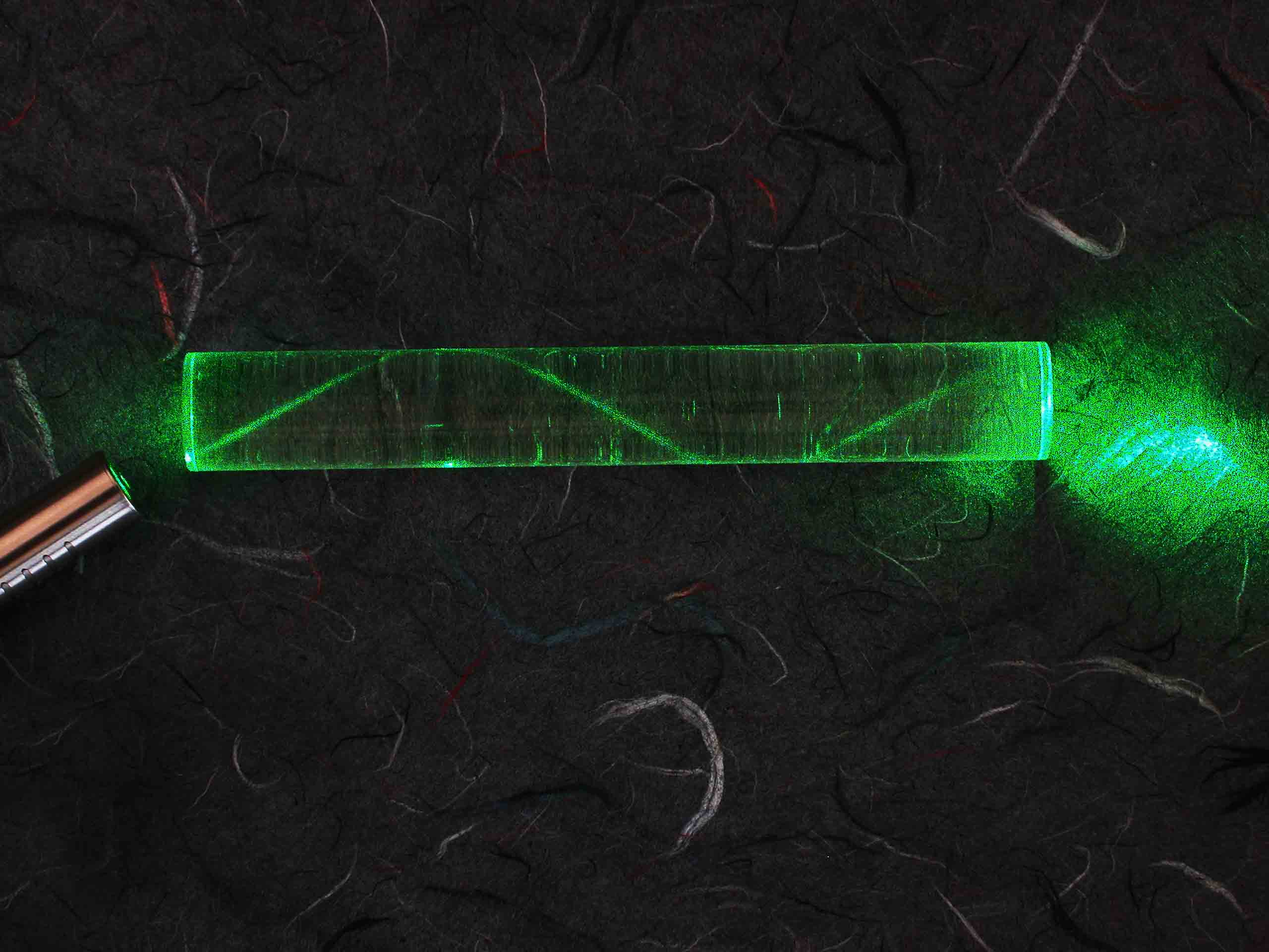
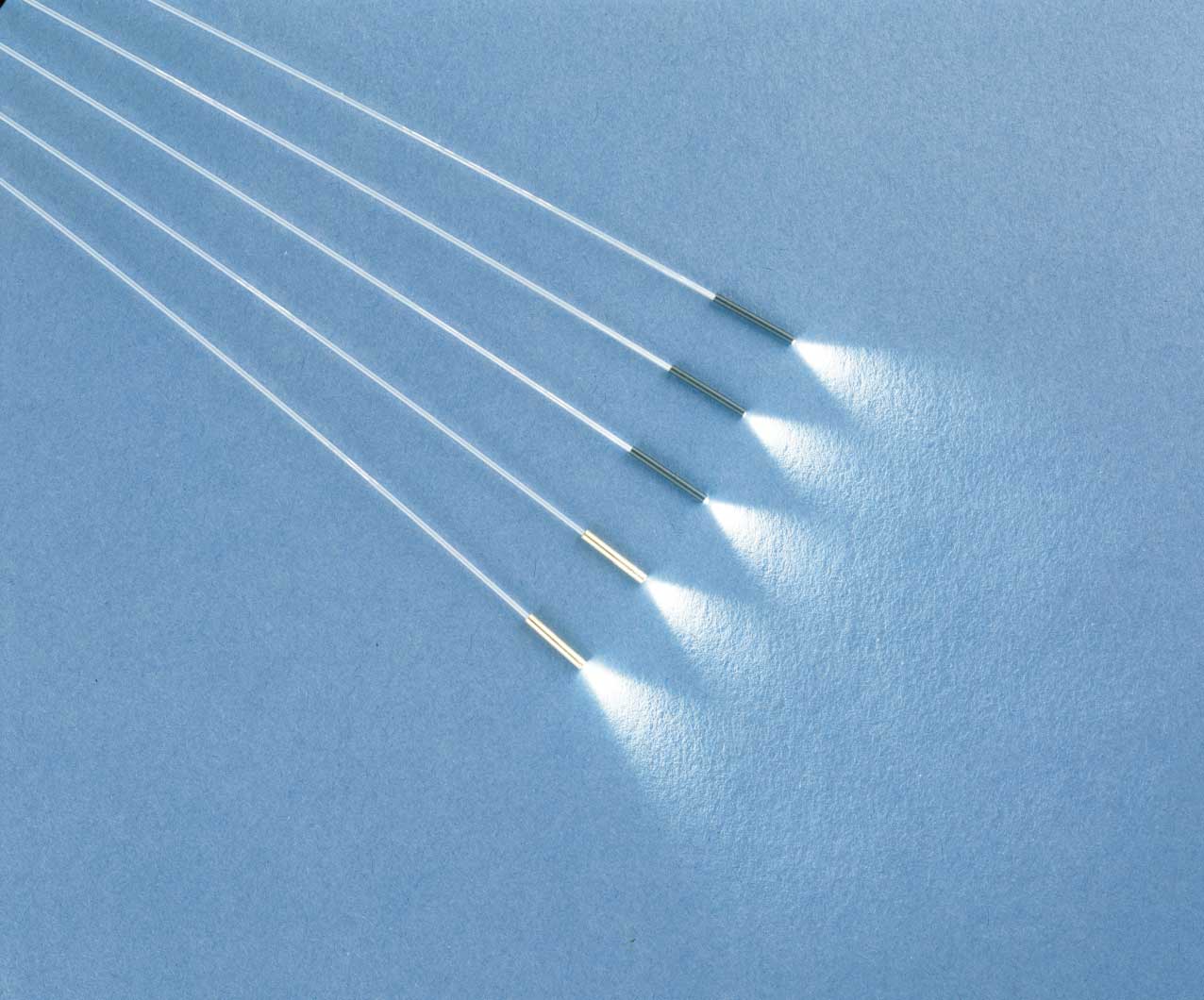
An optical fiber is a cylindrical dielectric waveguide (nonconducting waveguide) that transmits light along its axis, by the process of total internal reflection. The fiber consists of a core surrounded by a cladding layer, both of which are made of dielectric materials. To confine the optical signal in the core, the refractive index of the core must be greater than that of the cladding. The boundary between the core and cladding may either be abrupt, in step-index fiber, or gradual, in graded-index fiber. In the 1980's i research to coupling a high power 20 Watt argon laser beam in a glass fiber. The result was that the fiber itself in smoke dissolved. After incredible optical formula work i found the right combination.

The must consider the problem of matching the mode of the incident laser light in the problem of coupling light into an optical fiber is really two separate problems. In one case, we have the problem of coupling into multimode fibers, where the ray optics of the previous section can be used. In the other case, coupling into single-mode fibers, we have a fundamentally different problem. In this case, one to the mode of the fiber. This cannot be done using the ray optics approach, but must be done using the concepts of Gaussian beam optics.

Propagation of Gaussian beams through an optical system can be treated almost as simply as geometric optics. Because of the unique self-Fourier Transform characteristic of the Gaussian, we do not need an integral to describe the evolution of the intensity profile with distance. The transverse distribution intensity remains Gaussian at every point in the system; only the radius of the Gaussian and the radius of curvature of the wavefront change.
The depth of focus would increase 100 times to 16 mm. However, suppose we increase the focal length of the lens to 2,000 mm. The "focal spot size” given by our simple equation would be 200 times larger, or 1.6 mm, 60% larger than the original beam! Obviously, something is wrong. The trouble is not with the equations giving ω(x) and R(x), but with the assumption that the beam waist occurs at the focal distance from the lens. For weakly focused systems, the beam waist does not occur at the focal length. In fact, the position of the beam waist changes contrary to what we would expect in geometric optics: the waist moves toward the lens as the focal length of the lens is increased. However, we could easily believe the limiting case of this behavior by noting that a lens of infinite focal length such as a flat piece of glass placed at the beam waist of a collimated beam will produce a new beam waist not at infinity, but at the position of the glass itself.
(British spelling: fibres)
Optical fibers are a kind of waveguides, which are usually made of some kind of glass, can potentially be very long (hundreds of kilometers), and are – in contrast to other waveguides – fairly flexible. The most commonly used glass is silica (quartz glass, amorphous silicon dioxide = SiO2), either in pure form or with some dopants.Silica is so widely used because of its outstanding properties, in particular its potential for extremely low propagation losses (realized with ultrapure material) and its amazingly high mechanical strength against pulling and even bending (provided that the surfaces are well prepared).
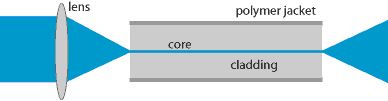 |
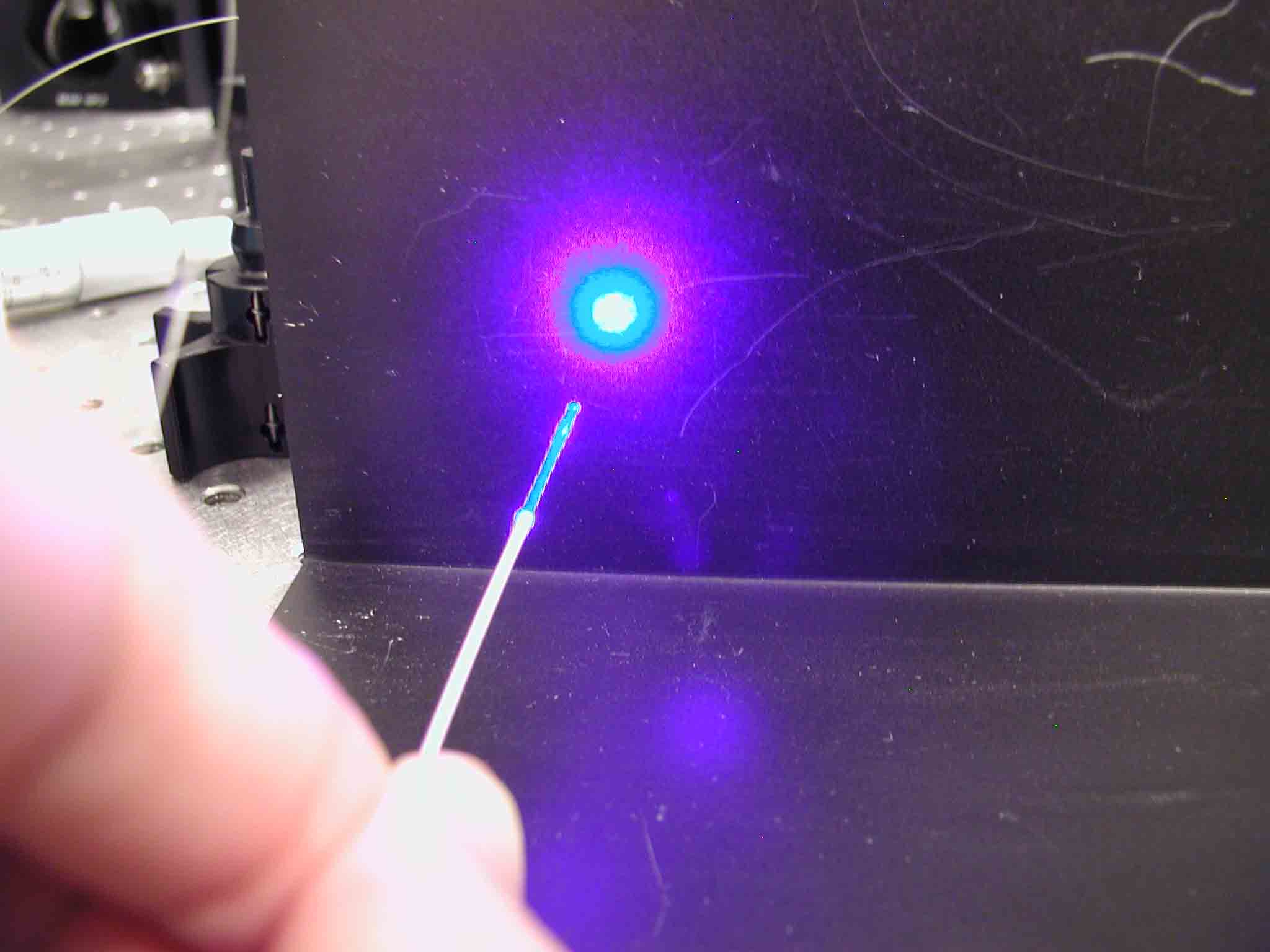
Simple setup for launching light into a glass fiber (not to scale). A collimated laser beam is focused into the fiber core. The light propagates along the core and leaves the other fiber end as a divergent beam. The fiber core and cladding are made of glass. A polymer jacket protects the fiber. | |
Most fibers used in laser optics have a core with a refractive index which is somewhat higher than that of the surrounding medium (called the cladding). The simplest case is that of a step-index fiber, where the refractive index is constant within the core and within the cladding. The index contrast between core and cladding determines the numerical aperture of the fiber (see below), and is typically small, so that fibers are weakly guiding. Light launched into the core is guided along the core, i.e., it propagates mainly in the core region, although the intensity distribution may extend somewhat beyond the core. Due to the guidance and the low propagation losses, the optical intensity can be maintained over long lengths of fiber.
A less frequently used principle of guiding light is based on a photonic bandgap (→ photonic bandgap fibers). For example, this can be realized with concentric rings of different refractive index, forming a kind of two-dimensional Bragg mirror.
Main Parameters
The design of a step-index fiber can be characterized with only two parameters, e.g. the core radius a and the refractive index difference Δn between core and cladding. Typical values of the core radius are a few microns for single-mode fibers and tens of microns or more for multimode fibers.
The design of a step-index fiber can be characterized with only two parameters, e.g. the core radius a and the refractive index difference Δn between core and cladding. Typical values of the core radius are a few microns for single-mode fibers and tens of microns or more for multimode fibers.
Instead of the refractive index difference, one usually uses the numerical aperture, defined as
which is the sine of the maximum acceptable angle of an incident beam with respect to the fiber axis (considering the launch from air into the core in a ray-optic picture). The NA also quantifies the strength of guidance. Typical values are of the order of 0.1 for single-mode fibers, even though actual values vary in a relatively large range. For example, large mode area single-mode fibers can have low numerical apertures below 0.05, whereas some rare-earth-doped fibers have values of 0.3 and higher for a high gain efficiency. NA values around 0.3 are typical for multimode fibers. The sensitivity of a fiber to bend losses strongly diminishes with increasing NA, which causes strong confinement of the mode field to the core.
Another frequently used parameter is the V number
which is a kind of normalized frequency. Single-mode guidance is achieved when the V number is below ∼ 2.405. Multimode fibers can have huge V values. The number of modes then scales with V2.
As a numerical example, consider a typical step-index silica fiber for single-mode operation in the 1.5-μm spectral region, with a cut-off wavelength of 1.3 μm and a numerical aperture of 0.1. The refractive index of the pure silica cladding at 1.5 μm is ∼ 1.444. The core index is ∼ 1.4475, i.e., the index difference is ∼ 0.0035. The core diameter is 10 μm, and the V number is 2.1.
Special Types of Fibers
So-called double-clad fibers can have a single-mode core and a multimode inner cladding, the latter transporting the pump light e.g. of a high-power fiber laser or amplifier.
There are various kinds of polarization-maintaining fibers, mostly realized on the basis of strong birefringence. The linear polarization of light is preserved provided that the initial polarization axis is aligned with a birefringent axis of the fiber. In addition, there are also single-polarization fibers (polarizing fibers) where one polarization direction experiences strong losses.
A special kind of optical fibers is the photonic crystal fiber (PCF), also called microstructure fiber or holey fiber. Such fibers typically consist only of a single material (usually silica), containing very small air holes with diameters well below 1 μm. Fabrication of such fibers is possible by using preforms with holes, made e.g. by stacking capillary tubes. By varying the arrangement of air holes, fibers with extremely different properties can be made, e.g.

-extremely large or small mode areas, leading to extremely weak or strong nonlinearity
-single-mode guidance in very large wavelength regions (endlessly single-mode fibers)
-guidance with the light field dominantly propagating in an air hole (air-guiding photonic bandgap fibers)
-unusual chromatic dispersion properties, e.g. anomalous dispersion in the visible spectral region
Photonic crystal fibers are now attracting strong interest for a wide range of applications, including extremely nonlinear fiber devices, soliton fiber lasers operating at short wavelengths, and high-power fiber amplifiers.
Although most fiber cores consist of some variant of silica (e.g. germanosilicate or aluminosilicate glass), other glass materials can also be used. Examples are
-phosphate glasses mainly for fiber amplifiers and lasers (low quenching tendency even for high rare earth doping concentrations)
-chalcogenide glasses (sulphide, telluride, or selenide glasses), having small phonon energies, mainly used for mid-infrared applications
-fluoride glasses, also with small phonon energies, used for mid-infrared and upconversion lasers
Low-cost multimode fibers can be made of polymers (plastic optical fibers, POF), which are cheap materials, allow simple production by extrusion, and are robust and flexible even when made with larger diameters. In some application areas, they allow for substantially cheaper solutions than possible with glass fibers. Even photonic crystal fibers can nowadays be produced from polymers. Some polymer fibers can also be used to guide terahertz waves.
In some cases, fibers are made of crystalline materials such as sapphire, but these fibers are usually not flexible and can be seen as thin rods using waveguide propagation (with or without a core structure at the center). They can be used for very high-power fiber lasers and amplifiers.
Polishing, Cleaving, and Splicing
Clean and smoothly shaped fiber ends can be produced with polishing techniques. These can also be used to produce end faces which are not perpendicular to the fiber axis. With a tilt angle of the order of 10° (angle polishing), reflections from fiber ends can be effectively eliminated from the beam path, so that e.g. reflection-sensitive lasers are well protected.
A much faster technique for preparing fiber ends is cleaving. Here, one typically pulls the fiber while scratching it from a side, e.g. with a vibrating diamond blade. This makes the fiber break with normally fairly smooth end faces – at least around the core region. By twisting the fiber during this process, angle cleaves can be fabricated, but the results are less reproducible than for polishing techniques.
Fibers (particularly those made of silica) can also be spliced together. One may use the technique of fusion splicing for making permanent fiber joints. A simpler technique is mechanical splicing, where the fiber ends are firmly held together by some mechanical means, but not fused. Here, however, the splice losses are typically higher, even when reduced with an index-matching gel between the surfaces.
There are also many types of fiber connectors which allow one to obtain good mechanical contact (as in a mechanical splice), but also to disconnect the fibers easily as required. Some more details are given in the article on fiber joints.
In general, the handling of fiber ends is fairly delicate, compared with the handling of electrical connections. Apart from problems with dust, grease and the like, fiber ends are relatively sensitive and are easily scratched. Their handling often requires very expensive equipment (e.g. high-quality fusion splicers), particularly when reliable results are required under field conditions, i.e., in a comparatively dirty environment. On the other hand, a fair comparison with electrical cables has to take into account the much higher transmission capacity of a fiber.
Fiber Modes – Single-mode versus Multimode Fibers
A fiber can support one or several (sometimes even many) guided modes, the intensity distributions of which are located at or immediately around the fiber core, although some of the intensity may propagate within the fiber cladding. In addition, there is a multitude of cladding modes, which are not restricted to the core region. The optical power in cladding modes is usually lost after some moderate distance of propagation, but can in some cases propagate over longer distances. Outside the cladding, there is typically a protective polymer coating, which gives the fiber improved mechanical strength and protection against moisture, and also determines the losses for cladding modes. Such coatings may consist e.g. of acrylate, silicone or polyimide.
An important distinction is that between single-mode and multimode fibers:
|
-
|
Single-mode fibers usually have a relatively small core (with a diameter of only a few micrometers) and can guide only a single spatial mode (disregarding the fact that there are two different polarization directions), the profile of which in most cases has roughly a Gaussian shape. Changing the launch conditions only affects the power launched into the guided mode, whereas the spatial distribution of the light exiting the fiber is fixed. Efficiently launching light into a single-mode fiber usually requires a laser source with good beam quality and precise alignment of the focusing optics in order to achieve mode matching. The mode radius of a single-mode fiber is often of the order of 5 μm, but there are also large mode area fibers with single-mode guidance. In the latter case, the alignment tolerances are lower in terms of position but higher in terms of angle (which may be less problematic).
|
|
|
|
-
|
Multimode fibers have a larger core and/or a larger index difference between core and cladding, so that they support multiple modes with different intensity distributions (Figure 2). In this case, the spatial profile of light exiting the fiber core depends on the launch conditions, which determine the distribution of power among the spatial modes.
|
|
|
|
|
|
|
|
 |
Electric field amplitude profiles for all the guided modes of a fiber with a top-hat refractive index profile (→ step index fiber). The two colors indicate different signs of electric field values. The lowest-order mode (l = 1, m = 0, called LP01 mode) has an intensity profile which is similar to that of a Gaussian beam. In general, light launched into a multimode fiber will excite a superposition of different modes, which can have a complicated shape.
 |
Long-range optical fiber communication systems usually use single-mode fibers, because the different group velocities of different modes would distort the signal at high data rates (→ intermodal dispersion). For shorter distances, however, multimode fibers are more convenient as the demands on light sources and component alignment are lower. Therefore, local area networks (LANs), except those for highest bandwidth, normally use multimode fiber.
Single-mode fibers are also normally used for fiber lasers and amplifiers. Multimode fibers are often used, e.g., for the transport of light from a laser source to the place where it is needed, particularly when the light source has a poor beam quality and/or the high optical power requires a large mode area.
Different modes of a fiber can be coupled via various effects, e.g. by bending or often by irregularities in the refractive index profile. These may be unwanted or purposely introduced, e.g. as fiber Bragg gratings. Waveguide theory shows that an important factor for the coupling between different fiber modes is the difference in their wavenumbers, which for efficient coupling has to match the spatial frequency of a coupling disturbance.
Refractive Index Profiles
The refractive index profile of fibers often deviates substantially from that of a step-index profile (with constant refractive index within the core):
Due to preferential evaporation of the dopant during the collapse of the preform (assuming that the preform is made with chemical vapor deposition, see below), there is often a pronounced index dip at the center. For single-mode fibers with small mode areas, this does not need to have a strong impact on the mode field distribution, which in most cases closely resembles a Gaussian shape.
Some fibers are made with graded index profiles (graded-index fibers) where the refractive index is gradually reduced away from the center, e.g. with a parabolic shape. Parabolic index profiles are useful e.g. for multimode fibers because they minimize intermodal dispersion (see below).
There are also "W profiles”, where the core is surrounded by a region with a refractive index lower than that of the cladding (depressed cladding). In principle, there can even be additional index steps, or combinations with smooth refractive index variations.
Triangular, trapezoidal and Gaussian index profiles are used for dispersion-shifted fibers.
Index profiles do not need to be cylindrical. For example, an elliptical core shape can provide increased birefringence (→ polarization-maintaining fibers) or even single-polarization guidance (→ single-polarization fibers) (see below).
Note that the definitions of the numerical aperture and consequently of the V number become somewhat ambiguous for non-rectangular index profiles.
In addition, there are so-called photonic crystal fibers (see below), where the refractive index profile is strongly structured.
Propagation Losses
The power losses for light propagating in a fiber can be extremely small, particularly for single-mode silica fibers as used in telecommunications. The resulting attenuation is typically dominated by Rayleigh scattering for short wavelengths and by multiphonon absorption at long wavelengths. Rayleigh scattering results from refractive index fluctuations, which are to some extent unavoidable in a glass, but can be strongly increased by concentration fluctuations in fibers with high numerical aperture. Other loss contributions come from inelastic scattering (spontaneous Brillouin scattering and Raman scattering), from absorbing impurities, and from fluctuations of the core diameter.
For silica fibers, the loss minimum occurs around 1.5–1.6 μm and can be below 0.2 dB/km (∼ 4.5% per km), which is close to the theoretical limit based on Rayleigh scattering in an amorphous glass material. There is often some loss peak around 1.4 μm, which can be largely eliminated, however, by carefully optimizing the chemical composition of the core so as to reduce the OH content (i.e. the concentration of hydroxyl bonds). Interestingly, fibers with high OH content can exhibit lower losses for ultraviolet light, whereas they exhibit pronounced loss peaks in the infrared spectral region.
Multimode fibers, and in general fibers with high numerical aperture, tend to have significantly higher propagation losses, essentially because the higher doping level of the core increases the scattering losses. Rare-earth-doped fibers also have much higher losses, but as more than some tens of meters of such a fiber are rarely used, this usually does not matter for their applications.
Polarization Properties
 |
Despite the typically cylindrical symmetry, fibers usually exhibit some amount of birefringence which can cause the polarization state of light to evolve in an uncontrolled way (→ polarization of laser emission). There are special polarization-maintaining fibers with a strong built-in birefringence to solve this problem. In addition, there are single-polarization fibers, which guide only light with one polarization direction. There are also various types of fiber polarization controllers, which allow one to adjust the state of polarization in a fiber. |
Dispersion Properties
As a result of the waveguide properties, the chromatic dispersion of a fiber can deviate significantly from its material dispersion, particularly when the mode area is small (→ waveguide dispersion). This makes it possible to obtain unusual dispersion properties by engineering the waveguide properties. For example, dispersion-shifted fibers can have near zero dispersion in the 1.5-μm spectral region, and there are dispersion-flattened fibers with small dispersion over a large wavelength range or dispersion-decreasing fibers. A particularly high design freedom exists for photonic crystal fibers.
As a result of the waveguide properties, the chromatic dispersion of a fiber can deviate significantly from its material dispersion, particularly when the mode area is small (→ waveguide dispersion). This makes it possible to obtain unusual dispersion properties by engineering the waveguide properties. For example, dispersion-shifted fibers can have near zero dispersion in the 1.5-μm spectral region, and there are dispersion-flattened fibers with small dispersion over a large wavelength range or dispersion-decreasing fibers. A particularly high design freedom exists for photonic crystal fibers.
The birefringence makes the group delay polarization-dependent; this is often called polarization mode dispersion. For multimode fibers, there is also intermodal dispersion, i.e., a dependence of the group velocity on the fiber mode, which may be minimized by choosing a suitable refractive index profile but is typically larger than the dispersion of single-mode fibers.
Fiber Fabrication
Most optical fibers are fabricated by pulling from a so-called preform, which is a glass rod with a diameter of a few centimeters and roughly 1 m length. Along its axis, the preform contains a region with increased refractive index, which will form the core. When the preform is heated close to the melting point in a furnace (oven), a thin fiber with a diameter of typically 125 μm and a length of many kilometers can be pulled from the bottom of the preform. Before the fiber is wound up, it usually obtains a polymer coating for mechanical and chemical protection.
The core of a fiber can be doped with laser-active ions, normally rare earth ions of erbium, neodymium, ytterbium, or thulium. When these ions are excited with suitable pump light, optical amplification occurs, which can be used in fiber lasers or amplifiers.

Example:
Light Amplification by Stimulated Emission of Radiation (LASER or laser) is a mechanism for emitting electromagnetic radiation, typically light or visible light, via the process of stimulated emission. The emitted laser light is (usually) a spatially coherent, narrow low-divergence beam, that can be manipulated with lenses.
In laser technology, "coherent light" denotes a light source that produces (emits) light of in-step waves of identical frequency, phase, and polarization. The laser's beam of coherent light differentiates it from light sources that emit incoherent light beams, of random phase varying with time and position. Laser light is generally a narrow-wavelength electromagnetic spectrum monochromatic light; yet, there are lasers that emit a broad spectrum of light, or emit different wavelengths of light simultaneously.
