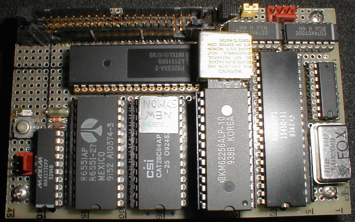
In the 60s and early 70s the first laser show scan controller developed on a thin plastic board used to hold electronic components (transistors, resistors, chips, etc.) that are wired together. Used to develop prototypes of electronic circuits, the boards can be reused for future jobs.
Early light shows relied on images created by mirrors attached to loudspeakers (Sonovision and others), scanning of the laser beam with motorised spinning mirrors, electromagnet-controlled springs and other techniques. While the early methods produced interesting and often repeatable scanned patters, they lack the precise control necessary to accurately position the beam.
The heart of the modern laser light show projector is the X-Y scanning system which allows for drawing with light to create abstract and cycloid effects. With today's precision, high-speed, position-detecting galvanometers, scanned graphics and animations are possible.
Lowell Cross, an electronic music composer, used X-Y images created on an oscilloscope tube to augment his music compositions while a graduate music student at the University of Toronto electronic music lab. The images were often created by modifying and displaying the actual sounds in the musical composition.
In an interview with the author, Cross stated, "I wanted to make the electronic music reproduction experience more involving for the audience than simply sitting watching the reels turn on the tape deck". To make the oscilloscope images larger and more interesting, he experimented first with black and white and later colour television sets modified for display of X-Y images.
A black and white television projector was also modified in 1965 to create a large size vector display. The projector only lasted one evening as the X-Y patterns became permanently etched on the CRT owing to the high intensity of the brightness levels permitted by Cross's modifications.
In 1968 Lowell Cross became acquainted with Carson Jeffries a sculptor of kinetic art systems (incorporating lasers) and a professor of physics. Cross and Jeffries set about building a laser projection system to display large scale images. On May 9, 1969 David Tudor, Carson Jeffries and Lowell Cross gave a concert at Mills College (Oakland California) with a multicolour X-Y laser projection system programmed by electronic music.
This very primitive (by today's standards) laser system used optical galvanometers from a Bell & Howell strip chart recorder, driven by Honeywell electronics and a Coherent CR-MG argon/krypton laser to project X-Y scanned images. Cross named his system Video/Laser. The images were programmed by the electronic music and the performance at Mills College was called Audio/Video/Laser. This is amongst the first true laser light shows. The promotion for the event stressed the laser content and Cross feels that as many people attended for the laser as for the music.
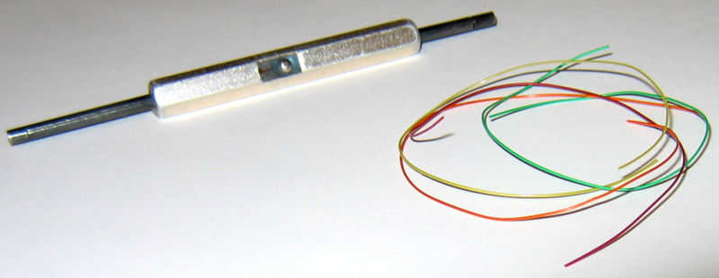
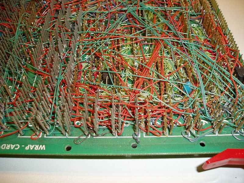
An early method of wiring circuit boards to each other. The boards were plugged into a backplane that contained metal prongs, which were wired together using a special tool. The tool stripped the end of the wire and coiled it around the prong. Thousands of computers were made with wire-wrapped methods.
Breadboards can also be used to create one-of-a-kind systems, although commercial products placed on printed circuit boards are typically much more robust and can handle greater frequencies. The breadboard contains spring clip contacts typically arranged in matrices with certain blocks of clips already wired together.
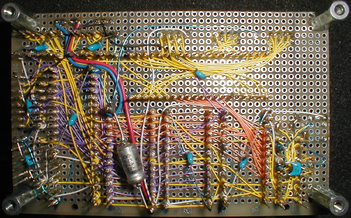
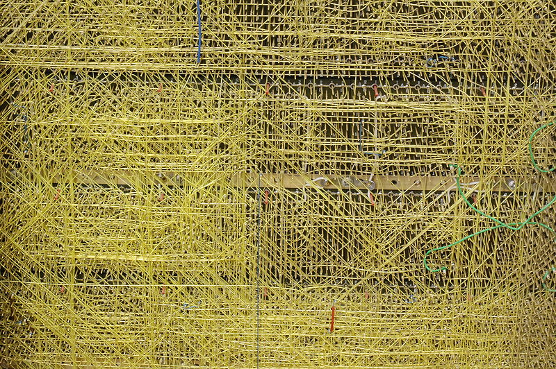
Wire wrap is a technology used to assemble electronics. It is a method to construct circuit boards without having to make a printed circuit board. Wires can be wrapped by hand or by machine, and can be hand-modified afterwards. It was popular for large-scale manufacturing in the 60s and early 70s, and continues to be used for short runs and prototypes. It is unusual among prototyping technologies in that very complex assemblies can be produced by automated equipment, and then easily repaired or modified by hand.
 |
Wire wrap construction can produce assemblies which are more reliable than printed circuits — connections are less prone to fail due to vibration or physical stresses on the base board, and the lack of solder precludes corrosion, cold joints, dry joints, etc. The connections themselves are firmer and have lower electrical resistance due to cold welding of the wire to the terminal post at the corners.
|
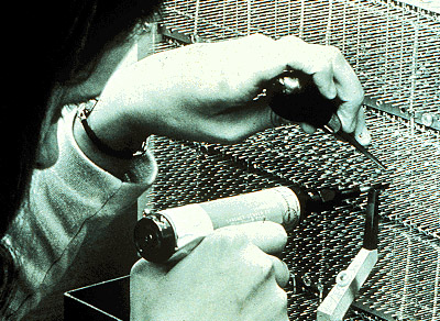
A correctly made wire-wrap connection is seven (7) turns of wire with 1.5 turns of insulated wire at the bottom for strain relief. The square hard-gold-plated post thus forms 28 redundant contacts. The silver-plated wire coating cold-welds to the gold. If corrosion occurs, it occurs on the outside of the wire, not on the gas-tight contact, because gold is more noble than silver. A correctly designed wire-wrap tool applies up to twenty tons of force per square inch on each joint.
Wire wrap was used for assembly of high frequency prototypes and small production runs, including gigahertz microwave circuits and super computers. It is unique among automated prototyping techniques in that wire lengths can be exactly controlled, and twisted pairs or magnetically-shielded twisted quads can be routed together.
Wire wrap construction became popular around 1960 in circuit board manufacturing, and use has now sharply declined. Surface-mount technology has made the technique much less useful than in previous decades. Solderless breadboards and the decreasing cost of professionally made PCBs have nearly eliminated this technology.
 |
In telecommunications wire wrap is in common high volume use in modern communications networks for cross connects between copper wiring plant. For example, most phone lines from the outside plant go to wire wrap panels in a central office, whether used for POTS phone service, DSL or T1 lines. Typically at a main distribution frame Internal Cross Facilities Assignments and External Cross Facilities Assignments, are connected together via jumpers that are wire wrapped. Wire wrap is popular in telecommunications since it is one of the most secure ways to attach wires, and provides excellent and consistent data layer contact. Wirewrap panels are rated for high quality data services, including Category 5 grade wiring. The principal competitor in this application is punch blocks, which are quicker but less secure.
|
Automated Wire Wrapping
Automated wire-wrap machines, as manufactured by the Gardner Denver Company in the 1960s and 1970s, were capable of automatically routing, cutting, stripping and wrapping wires onto an electronic "backplane" or "circuit board".
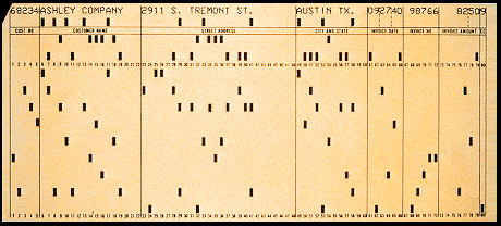 |
The machines were driven by wiring instructions encoded onto punched cards, Mylar punched hole tape, and early micro computers. The earliest machines (14FB and 14FG models, for example) were initially configured as "horizontal", which meant that the wire wrap board was placed upside down (pins up) onto a horizontal tooling plate, which was then rolled into the machine and locked onto a rotating (TRP table rotational position of four positions) and shifting (PLP = pallet longitudinal position of 11 positions) pallet assembly. |
These machines included very large hydraulic units for powering the servos that drove the ball screw mounted "A" and "B" drive carriages, a 6' tall electronics cabinet loaded with hundreds of IBM control relays, many dozens of solenoids for controlling the various pneumatic mechanical subsystems, and an IBM 029 card reader for positioning instructions. The automatic wire wrap machines themselves were quite large, 6 ft (2 m) tall and 8 ft (3 m) square. Servicing the machines was extremely complex, and often meant climbing inside them just to work on them. This could be quite dangerous if safety interlocks were not maintained properly; there were rumors throughout the industry that some fatalities/serious injuries had actually occurred. Later, somewhat smaller machines were "vertical" (14FV) which meant the boards were placed onto a tooling plate with pins facing the machine operator. Gone were the hydraulic units, in favor of direct drive motors to rotate the ball screws, with rotary encoders to provide positioning feedback. This generally provided better visibility of the product for the operator, although maximum wrap area was significantly less than the Horizontal machines. Top speeds on horizontal machines were generally around 500-600 wires per hour, while the vertical machines could reach rates as high as 1200 per hour, depending on board quality and wiring configurations.
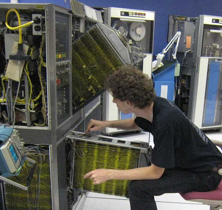
I at the Uni Bonn in 1985: Here I going after the problem. "We" were aware that relaxing the support rods would cause the problem, but I started to worry about the hinge area where the wires were routed into the gate. There is considerable stress/flexture at this hinge.
