Tuesday, 19.Mar.2024, 5:15:47
Welcome Guest | RSS


     Dr.(Phys.)Dipl.-Ing.Ralf-Udo Hartmann

Speedometer Reconstruction

Seite in deutscher Sprache
 
Through the overhaul of the 5 liter V8 engine, the question! How can I change the speedometer and the tachometer to the new parameters. In the search of an appropriate speedometer I finally found one on eBay.
 
The company SHK-Tacho gave me the best impression, and on the Intenet picture gallery of the company the correct speedometer unit was mapped W126.
 
 
After some consideration it was clear I order! You see it, the reconstruction of the speedometer is in laborious hand work. The printed film meets all the provisions of the German Road Traffic Regulations!
 
 
After 2 weeks of waiting I keep it in my hand. In the meantime, the revision of the engine was done, and I decided to expand the tachometer to 8000 rev / min. It is also clear that the engine should get a compressor and so I have the existing ECONOMY transform to a boost pressure indicator gauge! How ?? I tell you here!
 
 
I still had the old display group, and after a consultation with SHK-Tacho, I sent the display discs to Germany to change the layout. Since my car was made for the Japanese market, in which the old and new Speedo the speed information is specified in Miles and kilometers. But I wanted to use only the kilometer indication.


A few weeks later I received the discs with the new design. I must say SHK-Tacho has done excellent work exactly as specified. The result speaks for itself!
 
 
So the exchange of the disks can begin.
 

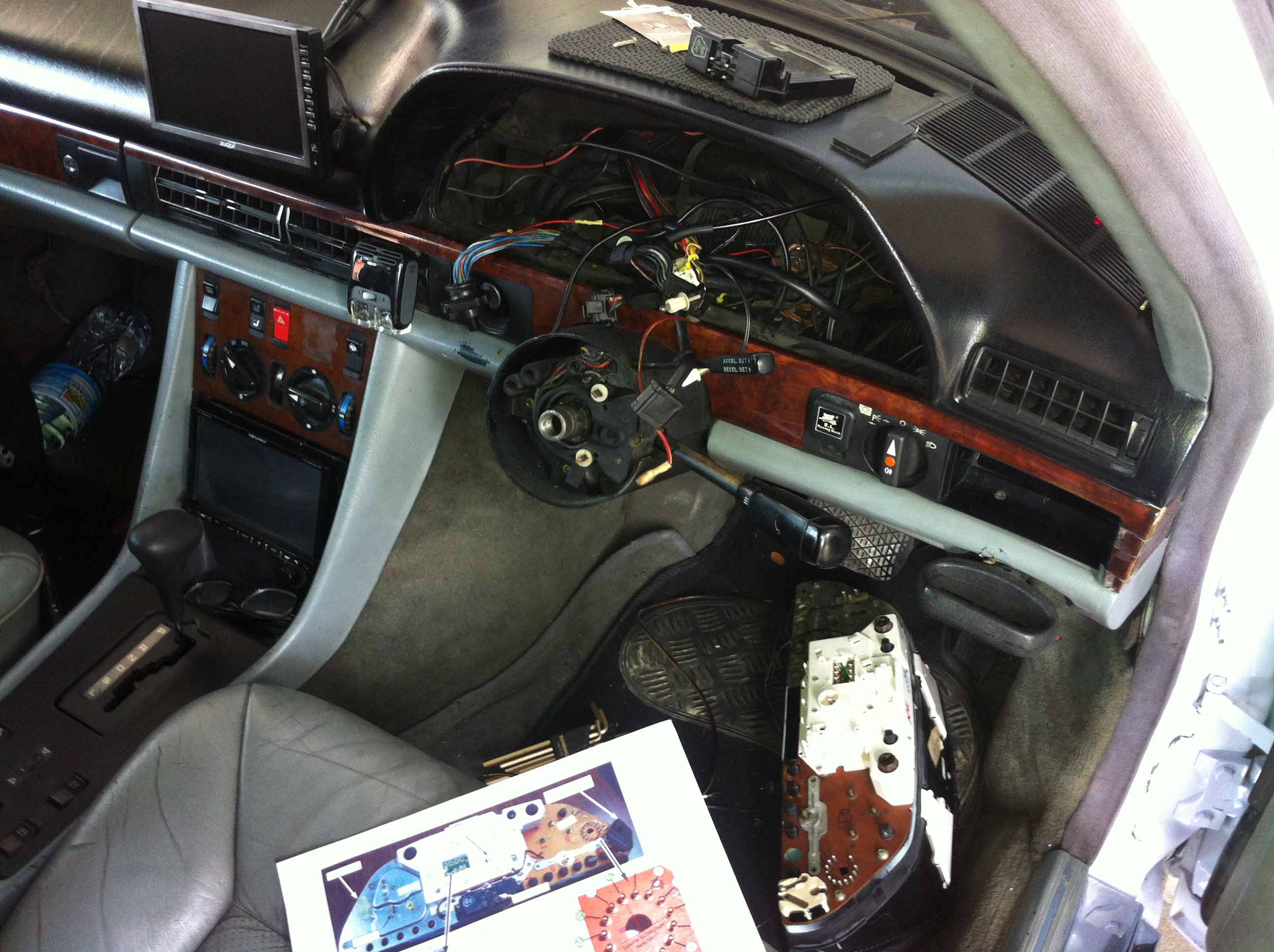
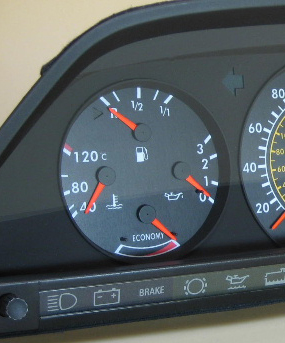
But we jump times back in time as I solved the problem with the ECONOMY ad! I have noted all the steps in image and video. Let's start with the left multifunction display


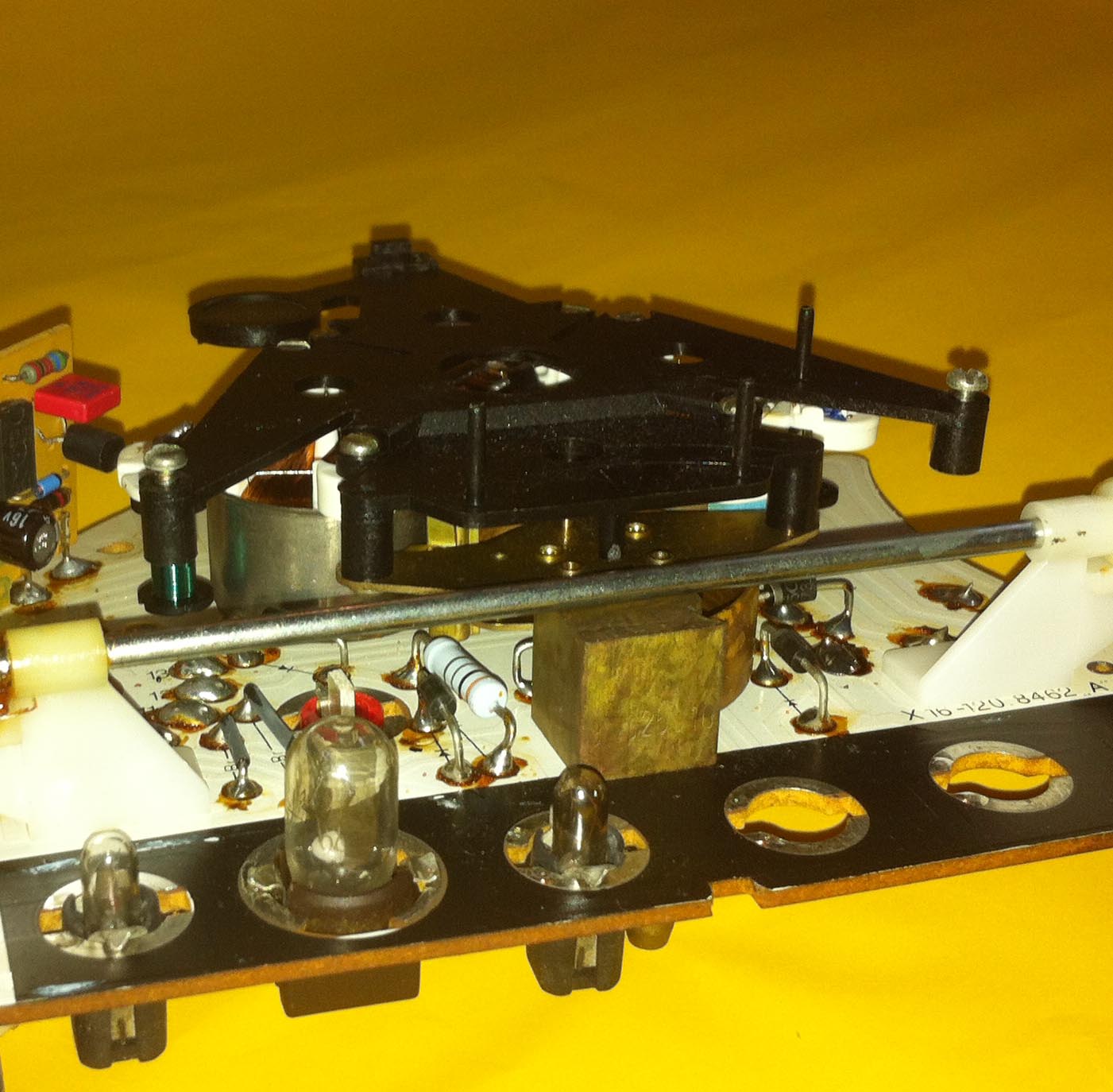
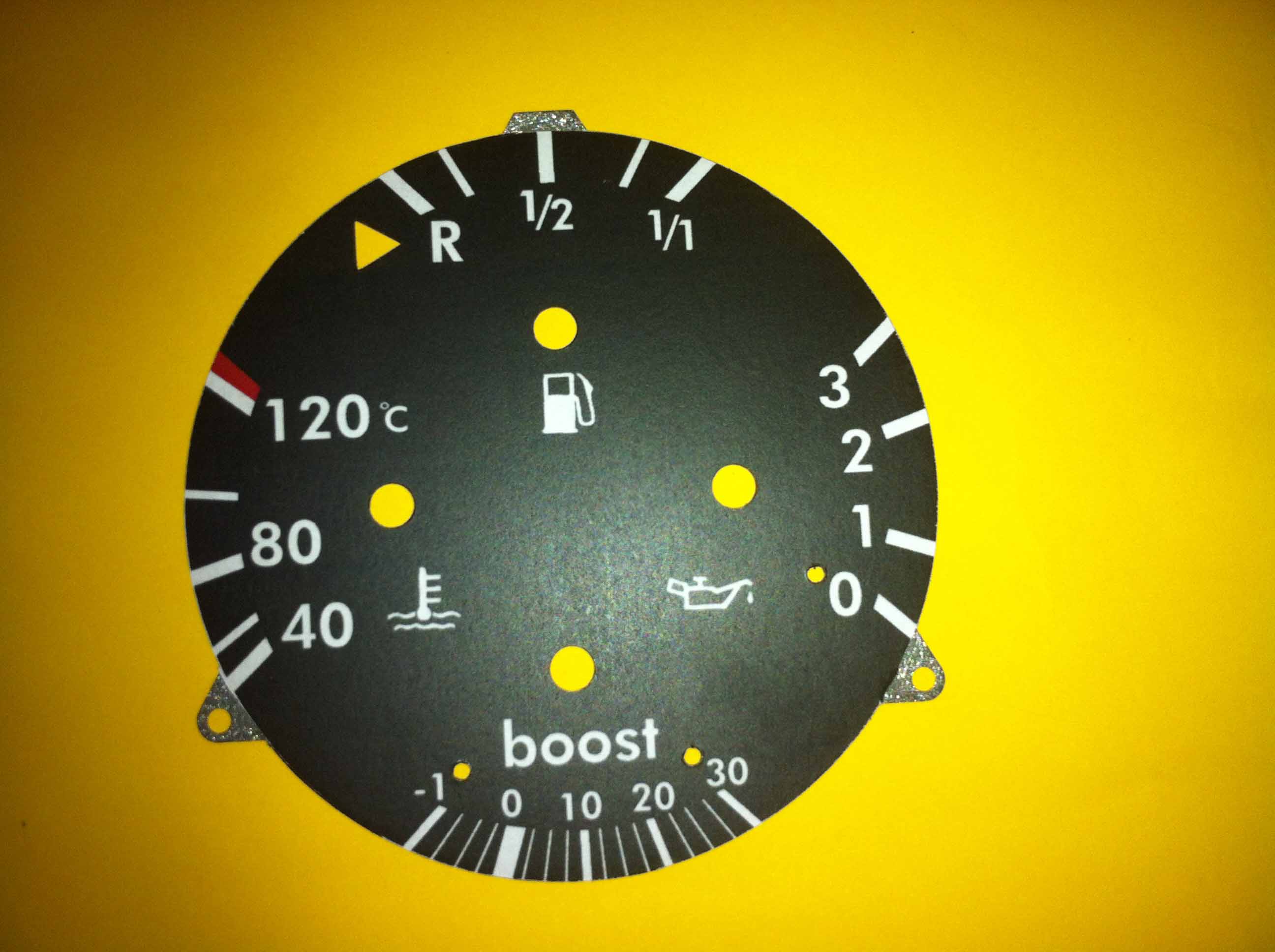
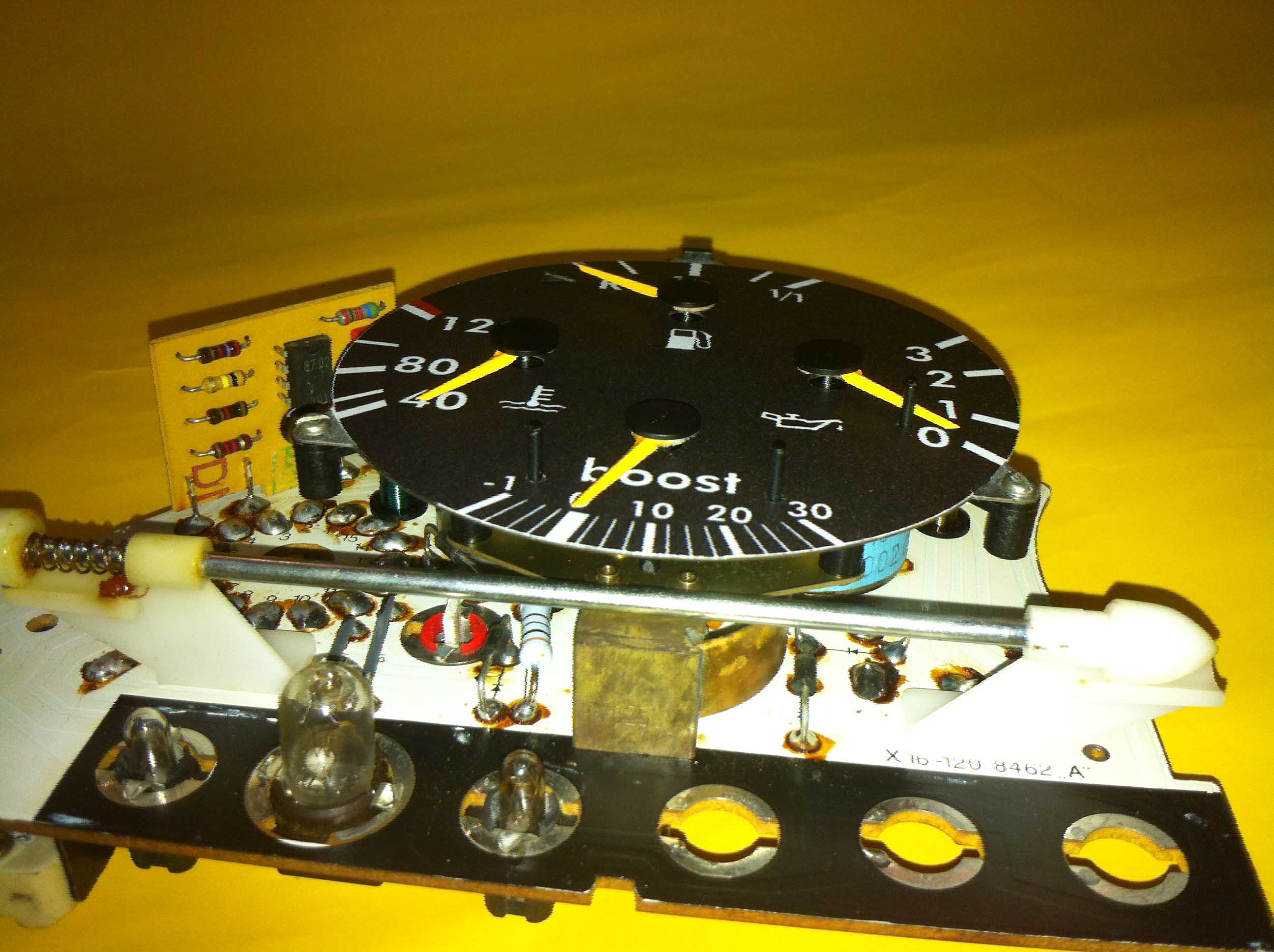
The ECONOMY display should also indicate the pressure of the compressor. The existing vacuum gauge should really also can show a positive pressure. So I have the component (the cube center right) looked at times more accurate.

Once viewed up close looks this purely mechanical component, after a good 30 years of faultless use, like new! A precision mechanical masterpiece.

So now once on the functioning and problems: The state of the engine sucks the air. The more compression the engine has the more negative pressure. If you can roll out the engine in gear, the display goes even higher, because when the throttle is to produce the piston a vacuum in the intake manifold. The throttle valve is in front of and behind the throttle valve prevails constant pressure. Under load and with increasing speed now increased by the mechanically driven compressor, the boost pressure. How exactly is this component behaves with increasing pressure in the intake manifold? This is to show a simple experiment.

In the experiment, I use a syringe to a vacuum build up and then switch to a pressure increase. In the video you can see how the pointer moves to the right when I pull the piston and thus producing a vacuum. If I press the piston into it now, I create a positive pressure and the pointer moves to the left. So the ECONOMY indicator can also show a positive pressure.

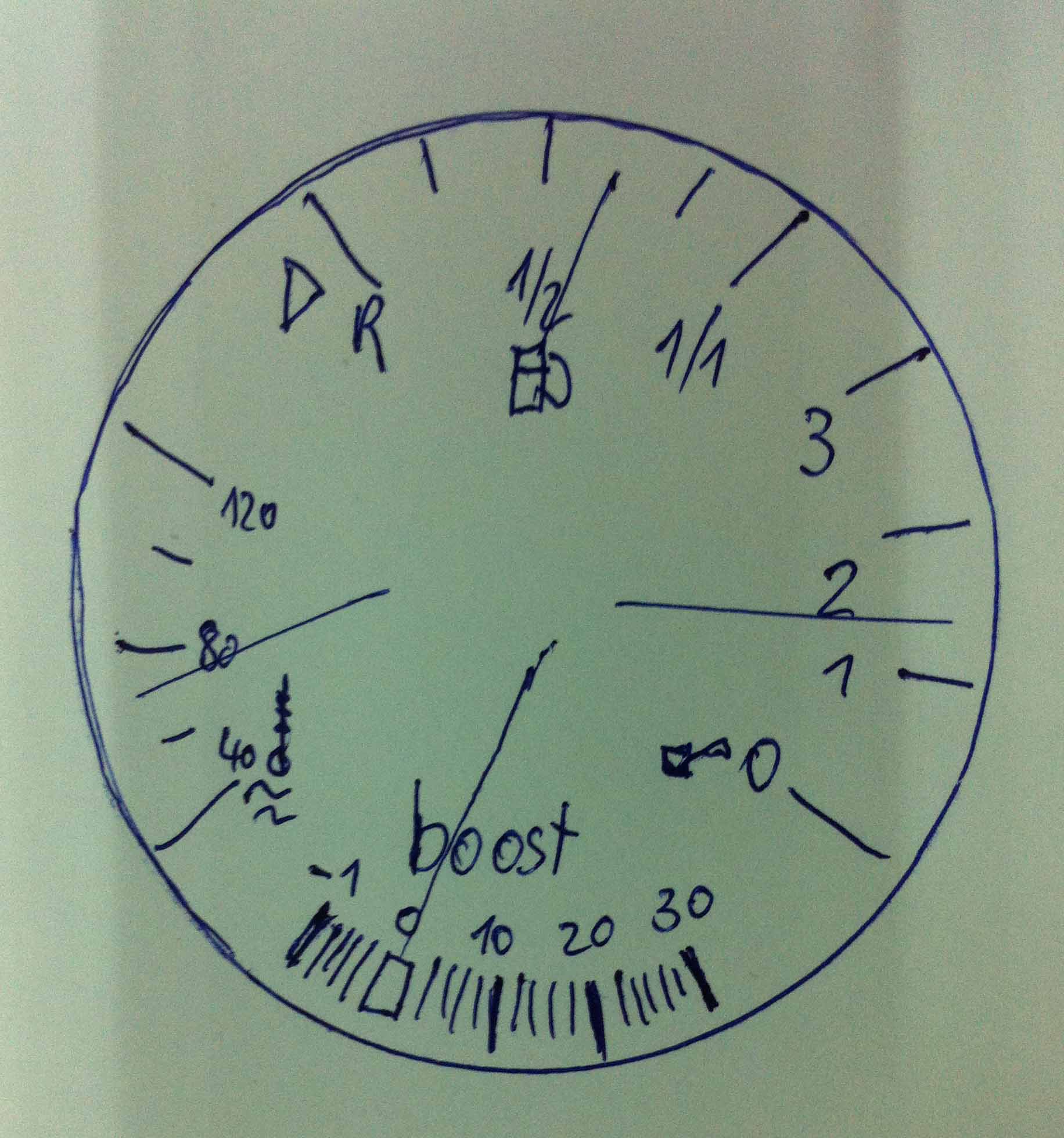
For comparison, the parameters I use a PRO-COMP meter. So I know in which hand position which pressure or vacuum is displayed. The individual hand positions I hold in a list and then create a preliminary sketch for the production of the disc.

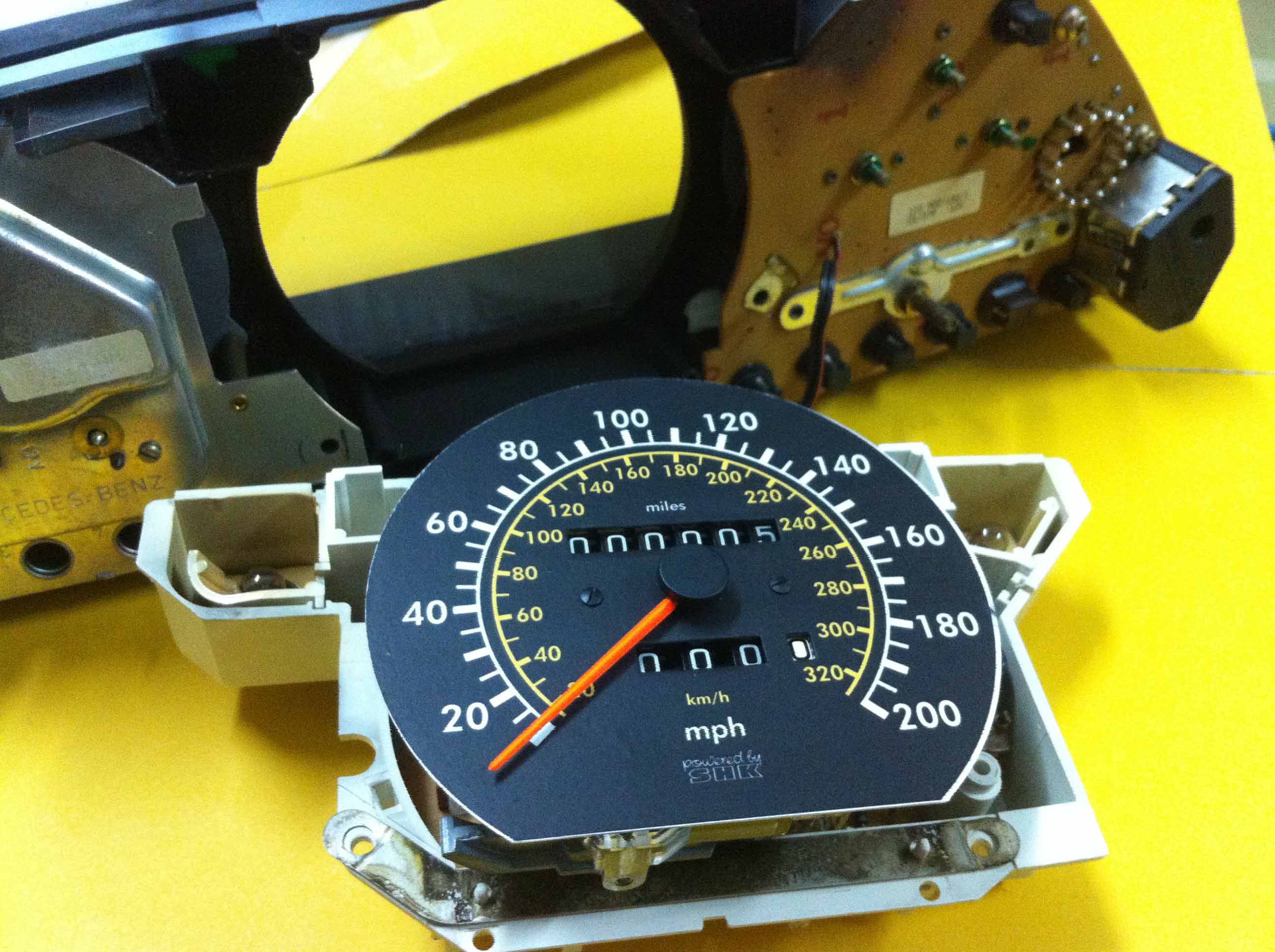
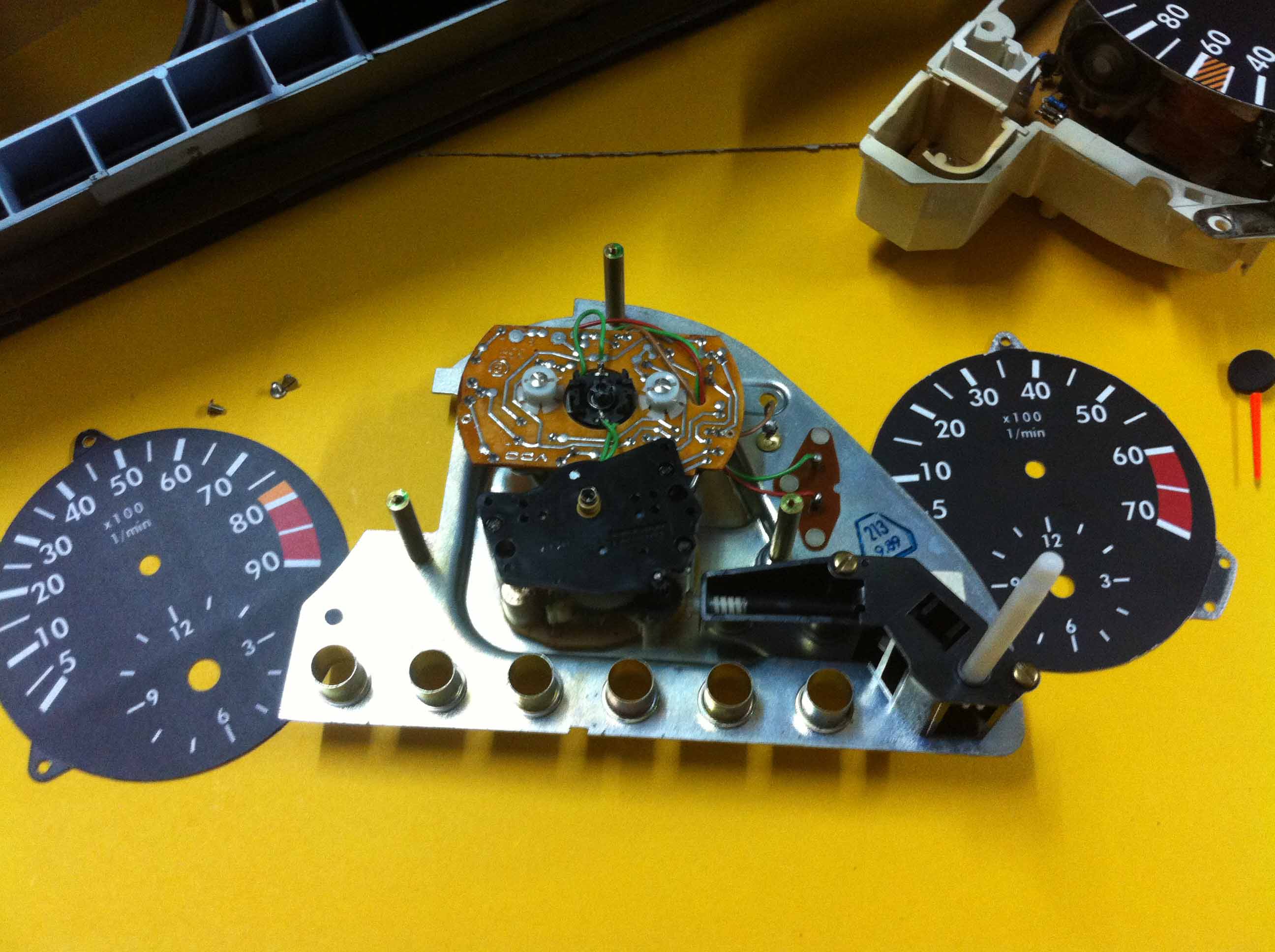
                    From design to digital template

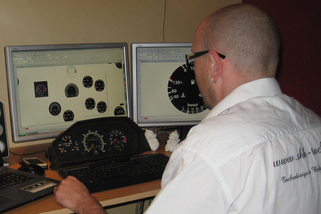
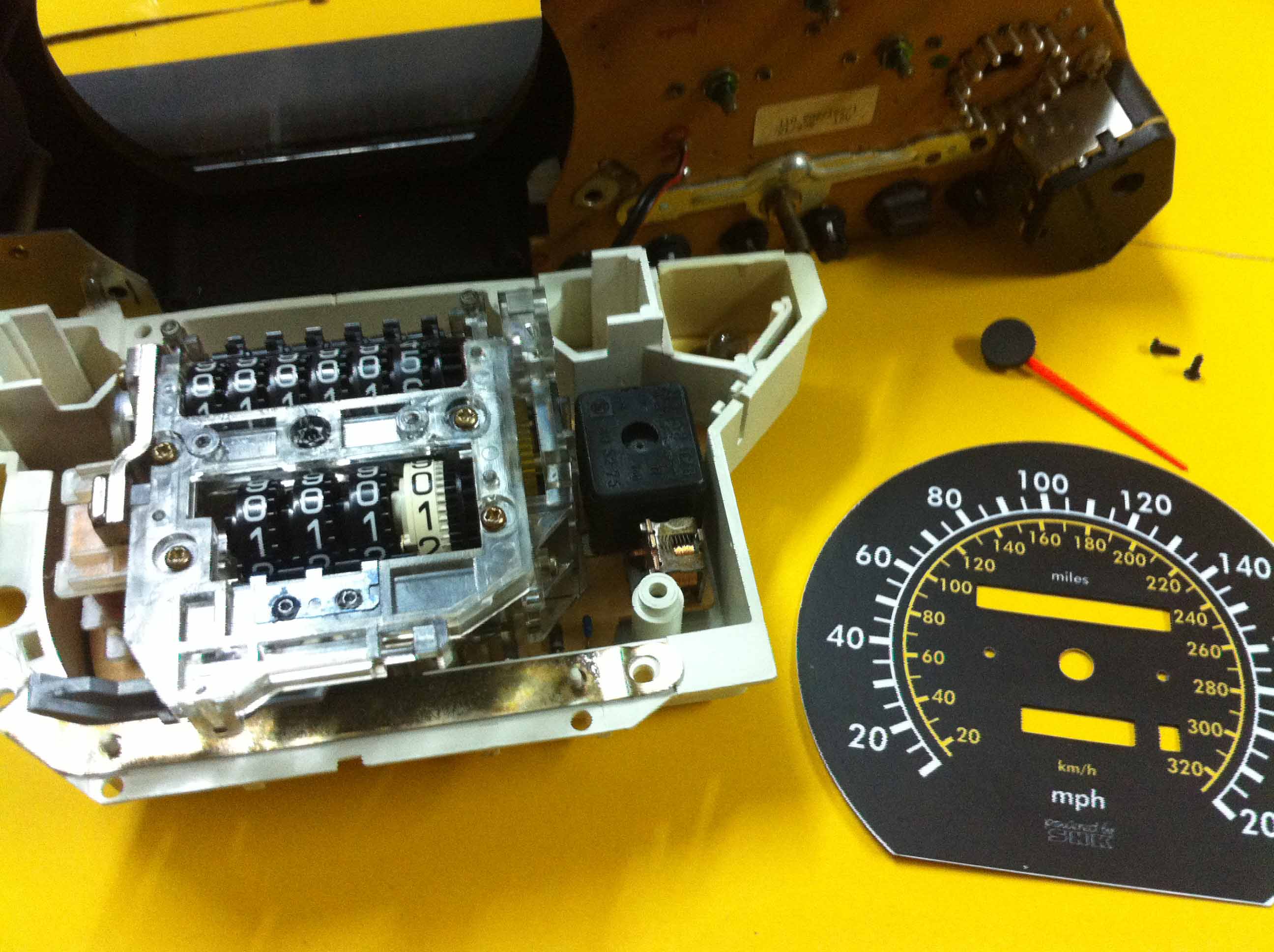
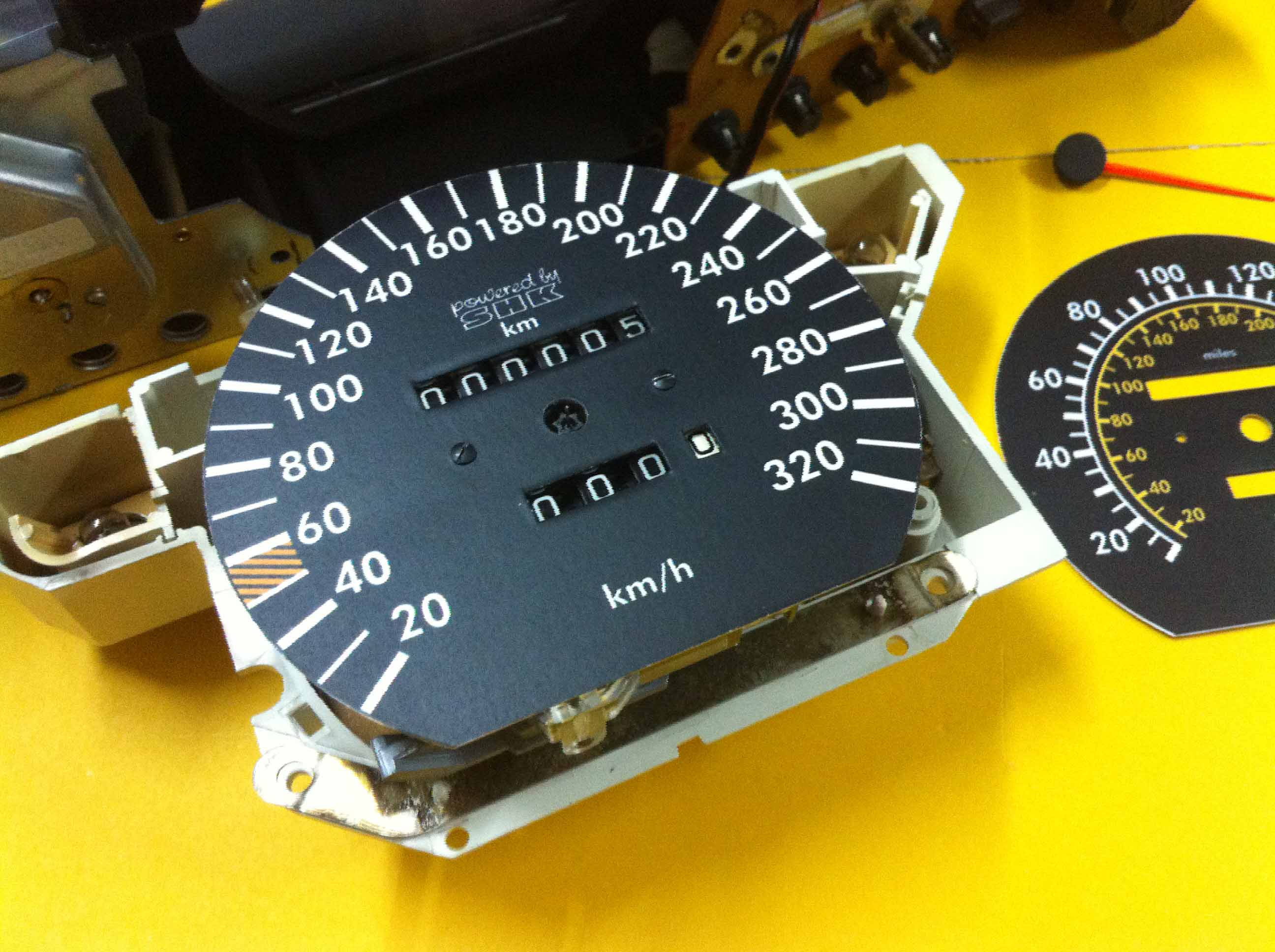
Here you can see Haris Kadic of www.shk-tacho.com in digitizing my freehand sketch. It is based on the design of a speedometer unit, to be seen in the foreground of the same type.

For the imagery i would like to thank! Sven and Haris Kadic!                                                    

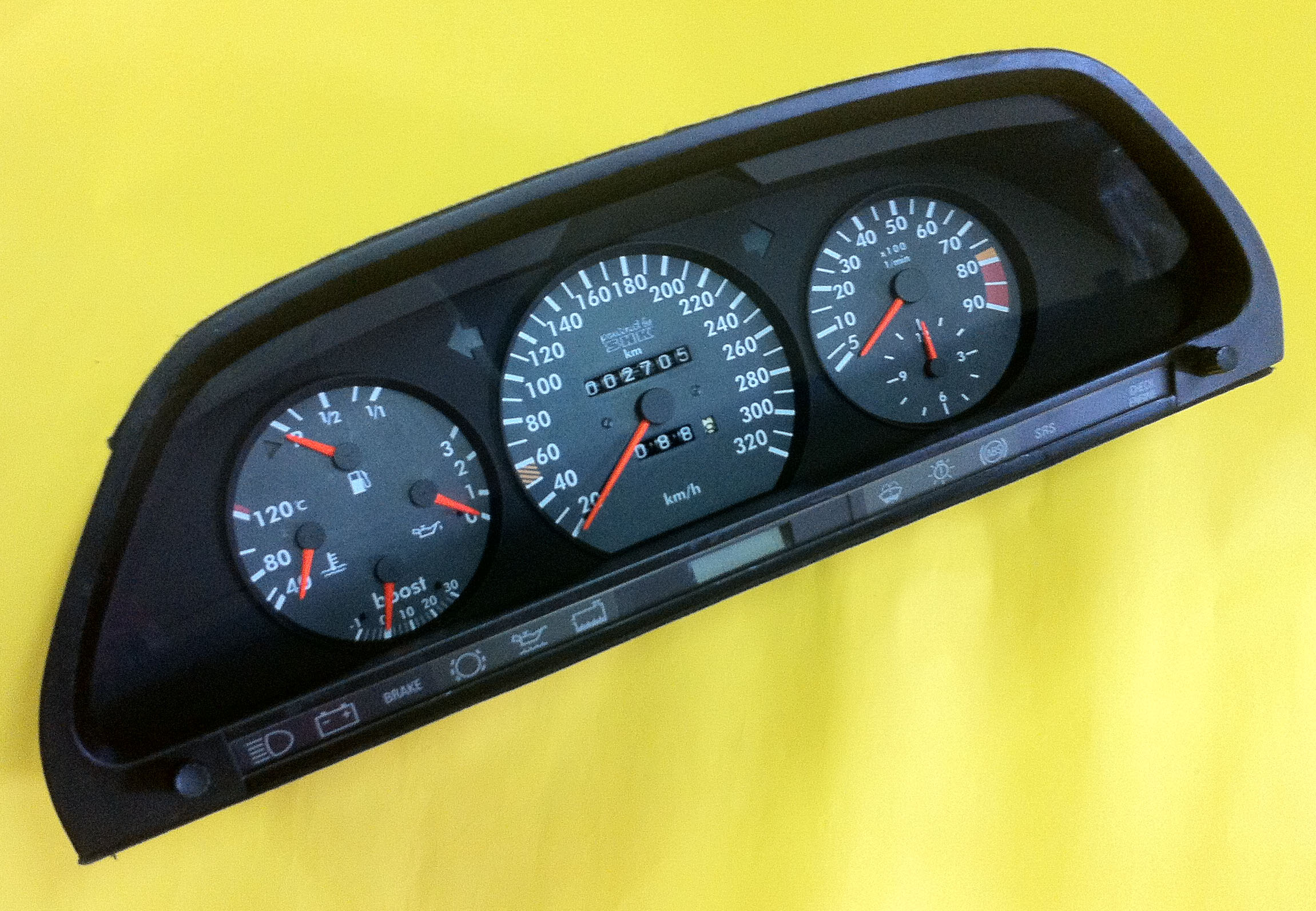
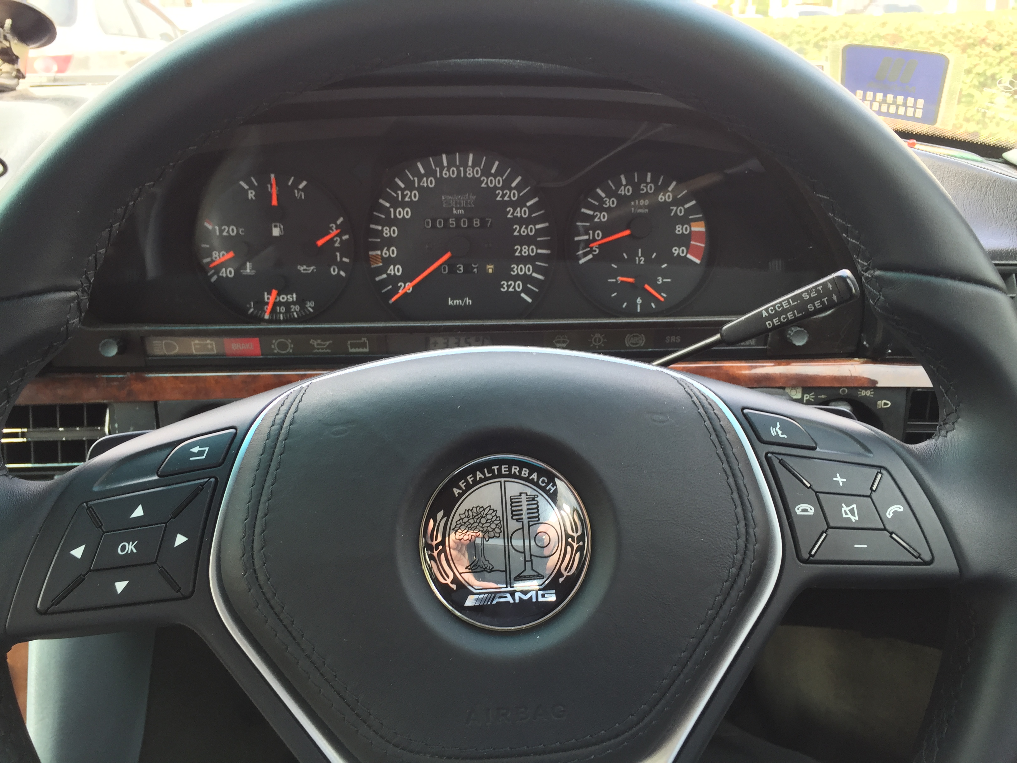
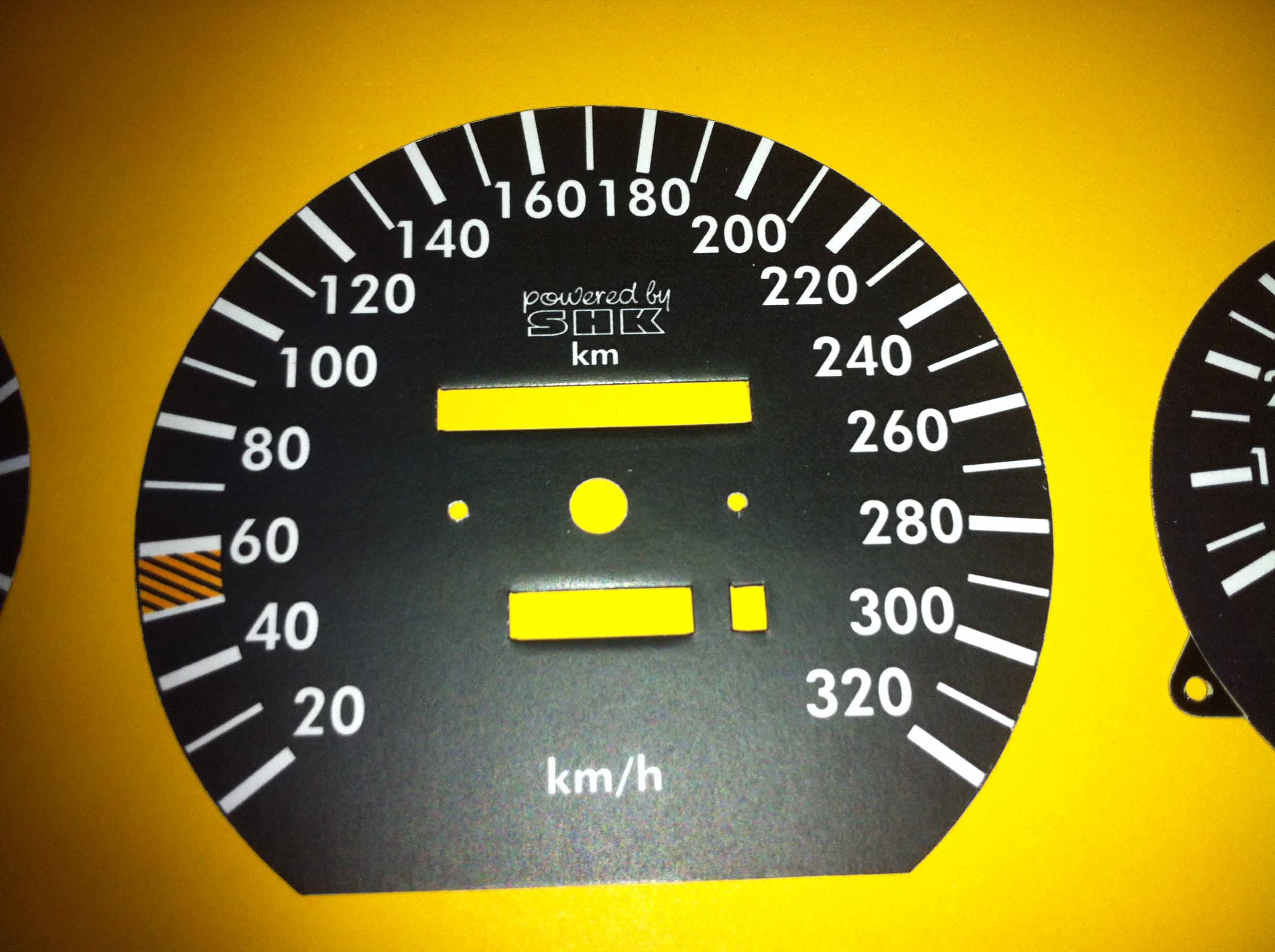
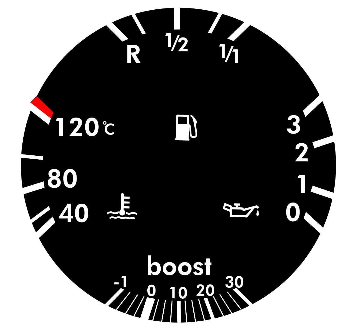
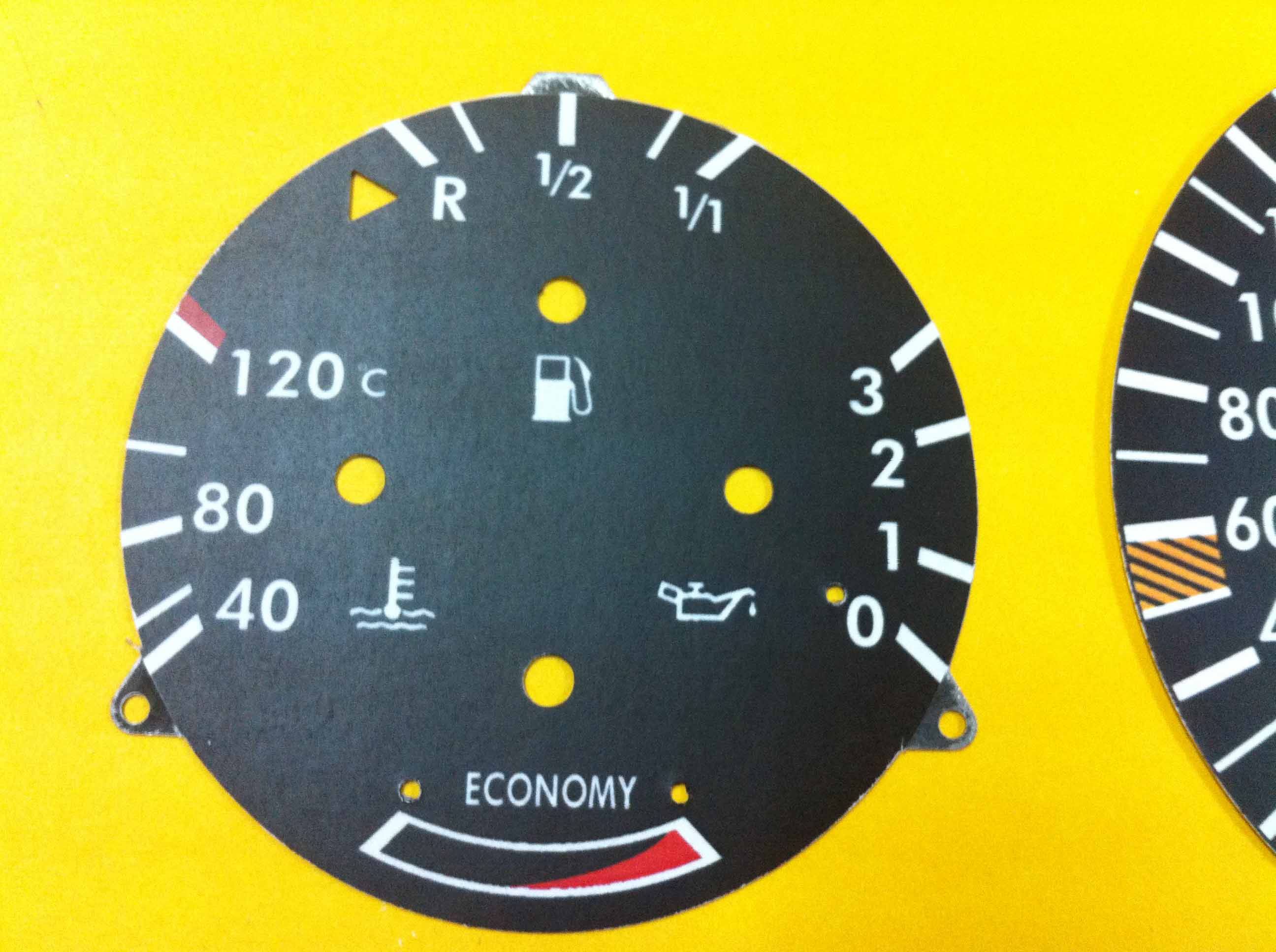
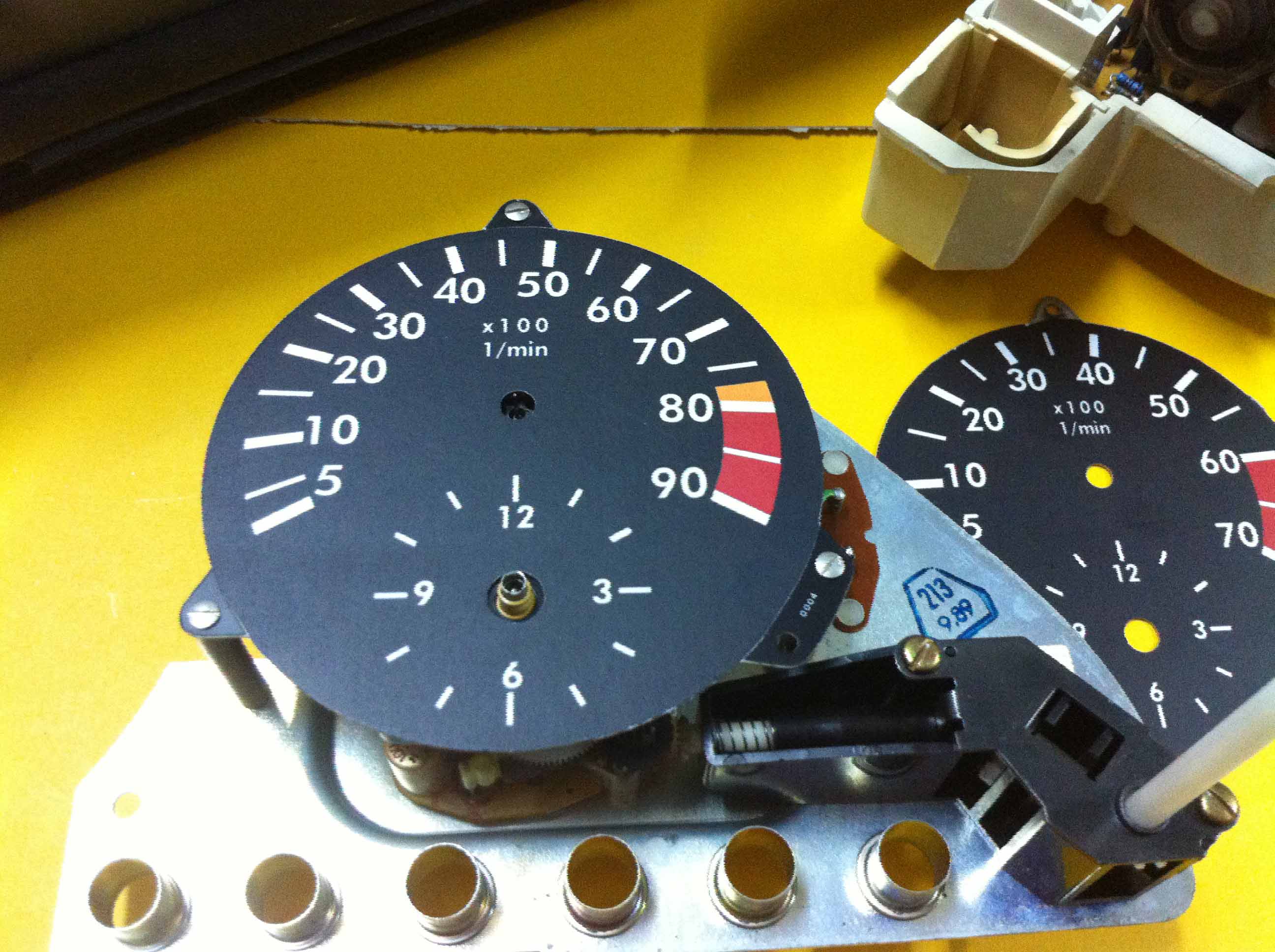
That was the preamble. Now finally can replace with the start of the discs. Here again, for comparison Economy version with the Boost version.

The pointer for the "boost" display is plugged into the zero position. Then, oil pressure, followed by cooling water and fuel gauge. Ready!!


Next, the speedometer: First, remove the pointer, followed by loosening the two retaining screws and remove the old disk with the combination printing of Miles and kilometers.
 
 
The next step: attaching the new disk with the imprint kilometers.
 
 
Now even attach the pointer and the speedometer is finished!


Finally, it is somewhat difficult. The rpm-meter and the clock is your turn. Remove pointer of the rev counter and the clock and undo the three screws that hold the plate in position.
 
 
In the picture you can see the electronics of the rpm-meter. This is later adjusted to the new Speed control of 9000 rpm/min
 
 
Attach the new disk imprinted with 9000 rpm/min with the three screws.
 
 
Attach the pointers for the rpm-meter and the clock and the complete display can be assembled.


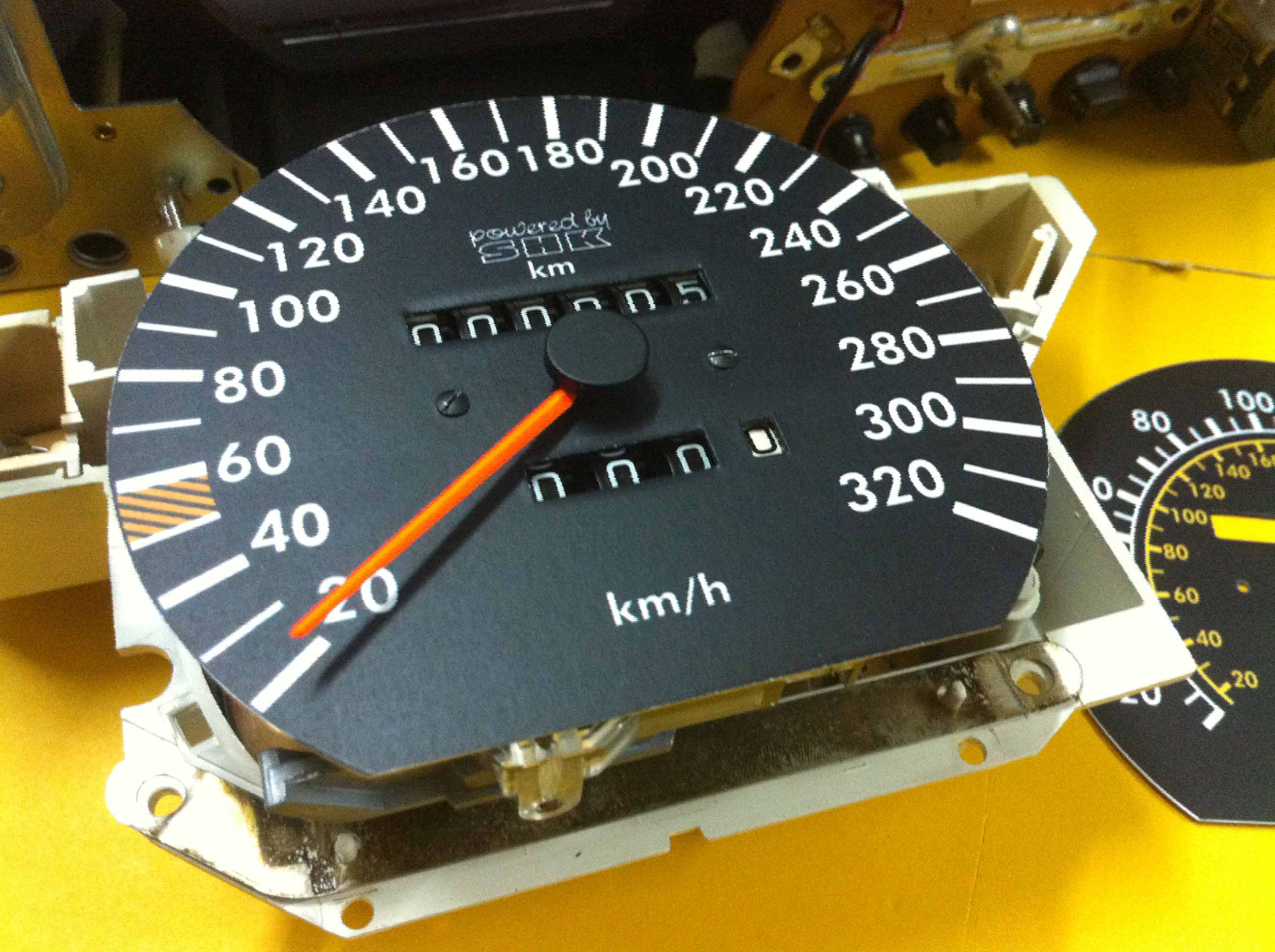
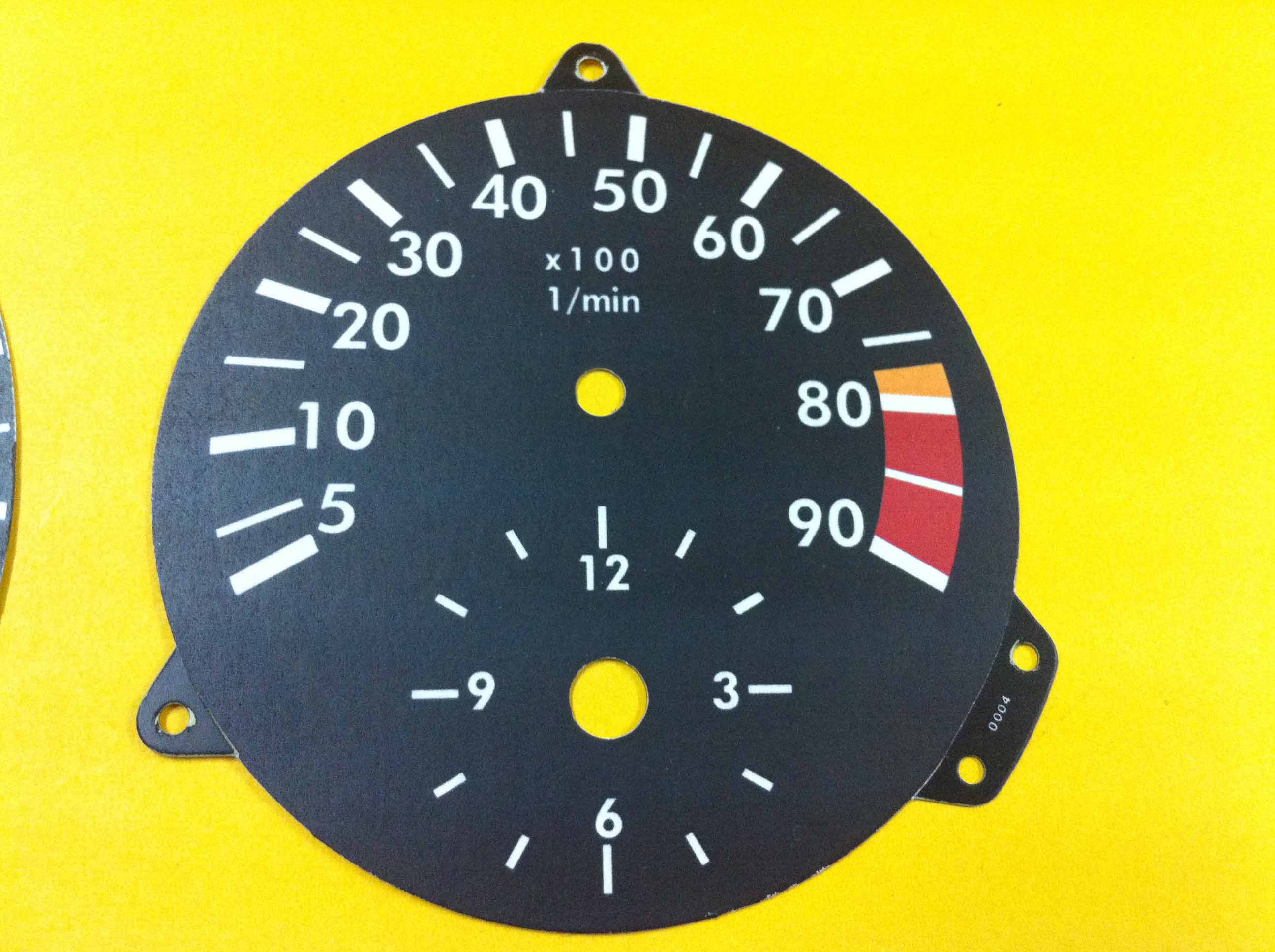
Only the tachometer at 9000 rpm/min Syndicate!

What you need:

A first transformer having primary and secondary 220V 5 -15V (a halogen lamp or bell transformer)

A second rectifier as B80C1500 etc.

A third resistor 10K / 0.5W

The secondary side of the transformer is connected to the AC input of the rectifier. The resistor is soldered between the DC outputs of the rectifier. The (-) output of the rectifier is connected to ground of the tachometer, the (+) output of the rectifier is connected to terminal (TD) of the tachometer. Furthermore, the tachometer via terminal is to supply (+) and ground with 12V DC voltage.

What appears and, when necessary.

Using the Trimmers must be set:

4-cylinder = 3000 1 / min

6-cylinder = 2000 1 / min

8-cylinder = 1500 1 / min

If a transformer supplied with mains voltage, so is the rpm-meter at a frequency of 100Hz. About the 22K trimmer on the board can now synchronize the rpm-meter (Located almost exactly behind the terminals (+) and (TD).


I have finally found the time on Saturday to install my new speedometer. I never expected that so it degenerates into work, not just the cable connections. I had to change the outside temperature display of the old module in to the new module. Finally, there was also a few little things to change.
 
 
Despite that I had detailed documentation for the correct wiring, but some fuses had to die. In the end I did it.
 
 
I think the results speak for themselves.
 
Go Back 
Menue
Statistics
Test your Internet connection speed at Speedtest.net

Search
Entries archive
Calendar
«  March 2024  »
SuMoTuWeThFrSa
     12
3456789
10111213141516
17181920212223
24252627282930
31
Search